The Mathematical Model Behind the Slicer
Recently, I have been building a slicer that calculates volumes for PolyVoxel. This gave me the opportunity to deep dive into how 3D models are built and, most importantly, the mathematics behind them.
So in this blog post, I will be diving deep into the mathematical model behind a slicer. The primary goal of the slicer that we built was to calculate the materials that will be used to print a model.
If we know the density (\rho) of the material that is used and the volume (V) of the model, we can easily calculate the mass of the model using the formula:
\rho = \frac{m}{V}
What is a 3D Model ?
A 3D model is a digital object that exists in a three-dimensional space. It is usually built from polygons, most commonly triangles or quadrilaterals. These polygons define the surface of the object by connecting vertices with edges and faces.
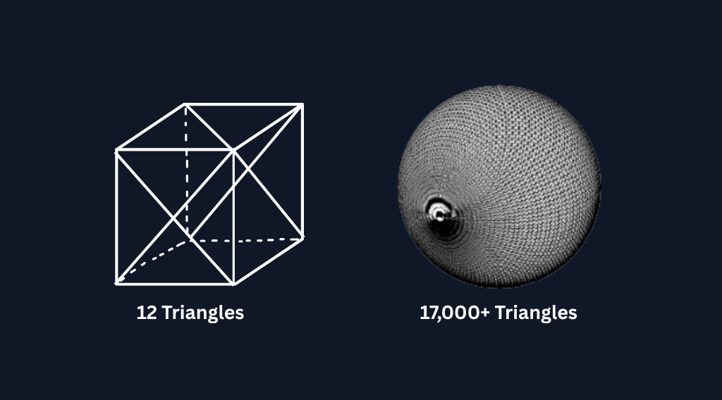 Image credit: Photo by Protolabs on What is an STL File?.
What are all these file formats ?
3D models can be stored in various file formats, each with its own way of representing the 3D geometry. Some common file formats include:
- STL: Represents the surface geometry of a 3D object using a mesh of triangles. It does not include color, texture, or other attributes.
- OBJ: Supports both polygonal and freeform geometry. It can include texture maps and material properties as well. … and many more.
In summary, all these file formats are just different ways to represent the 3D geometry of an object.
Okay, so how do we calculate the volume ?
To answer that question, let’s first consider the simplest file format of the above 3D files: the STL file.
Why is the STL file so simple and commonly used ?
The STL file contains only triangles, so the entire model is built up by joining triangles. Triangles are the simplest polygons, so it would be logical if we started from here. I am not saying that other file formats do not contain triangles; they may or may not contain triangles, but STL files only contain triangles.
Okay, now that is out of the way, let’s get to the interesting part : calculating the volume of a 3D model made up of triangles.
For starters, let’s consider all the vertices of the triangles as vectors in the 3D space. This can be done because any point in 3D space can be denoted as a vector. https://en.wikipedia.org/wiki/Three-dimensional_space.
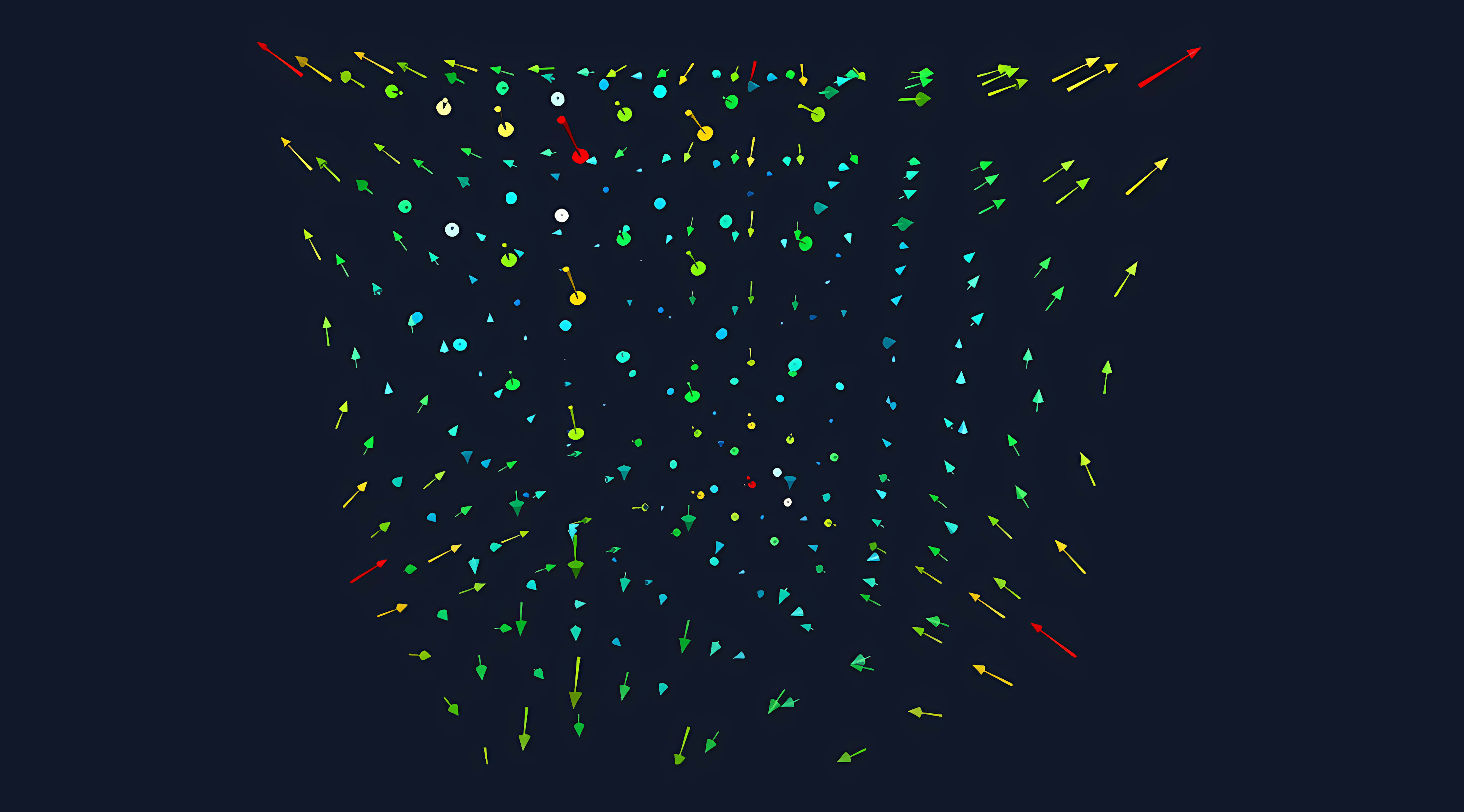
Image credit: Photo by 3Blue 1Brown on Essence of linear algebra.
Let’s consider a triangle with vertices A, B and C. We can denote these vertices as vectors A, B and C.
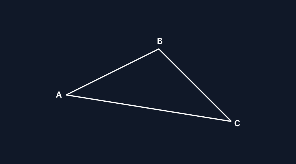
Let A be \begin{bmatrix} x_1 \\ y_1 \\ z_1 \end{bmatrix}, B be \begin{bmatrix} x_2 \\ y_2 \\ z_2 \end{bmatrix} and C be \begin{bmatrix} x_3 \\ y_3 \\ z_3 \end{bmatrix}.
Let’s consider the matrix M formed by these vectors as columns:
M = \begin{bmatrix} x_1 & x_2 & x_3 \\ y_1 & y_2 & y_3 \\ z_1 & z_2 & z_3 \end{bmatrix}
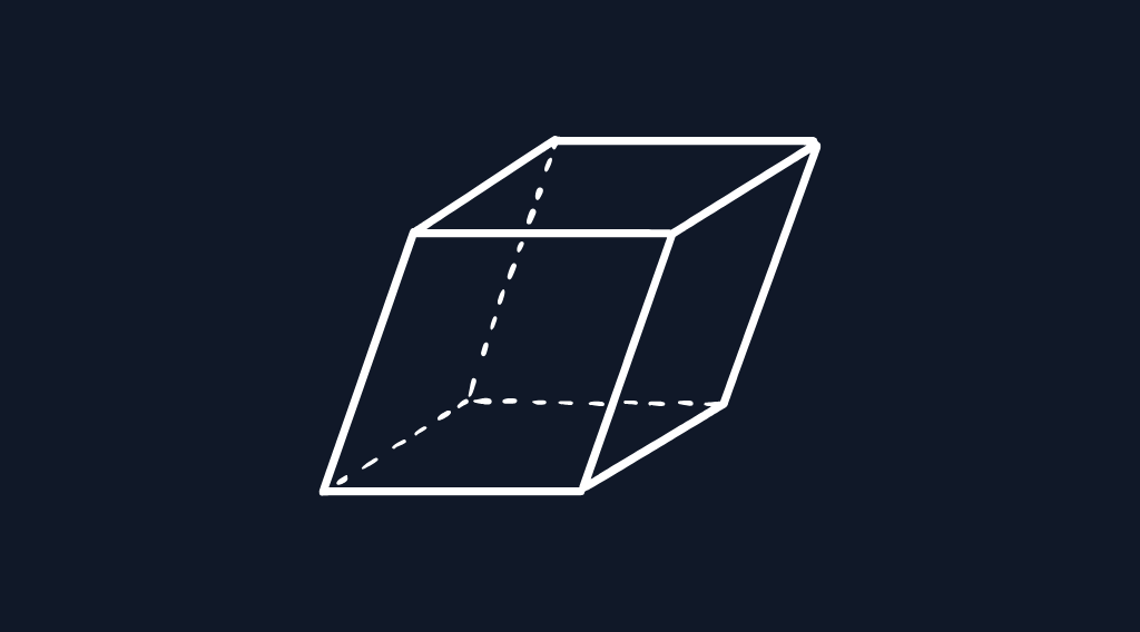
When we are considering the 2D plane the determinant of a matrix gives us the area of the parallelogram formed by the vectors. In 3D space, the determinant of a matrix gives us the volume of the parallelepiped formed by the vectors.Since all of these vectors originate from the origin and represented in terms of basis vectors, the parallelepiped formed is associated with the origin.
I can’t do a decent job of explaning this concept, so I would recommend watching 3Blue 1Brown’s video on Determinants.
So the volume of the parallelepiped formed by the vectors A, B and C is given by the formula:
V_{parallelepiped} = |det(M)|
Where det(M) is the determinant of the matrix M.
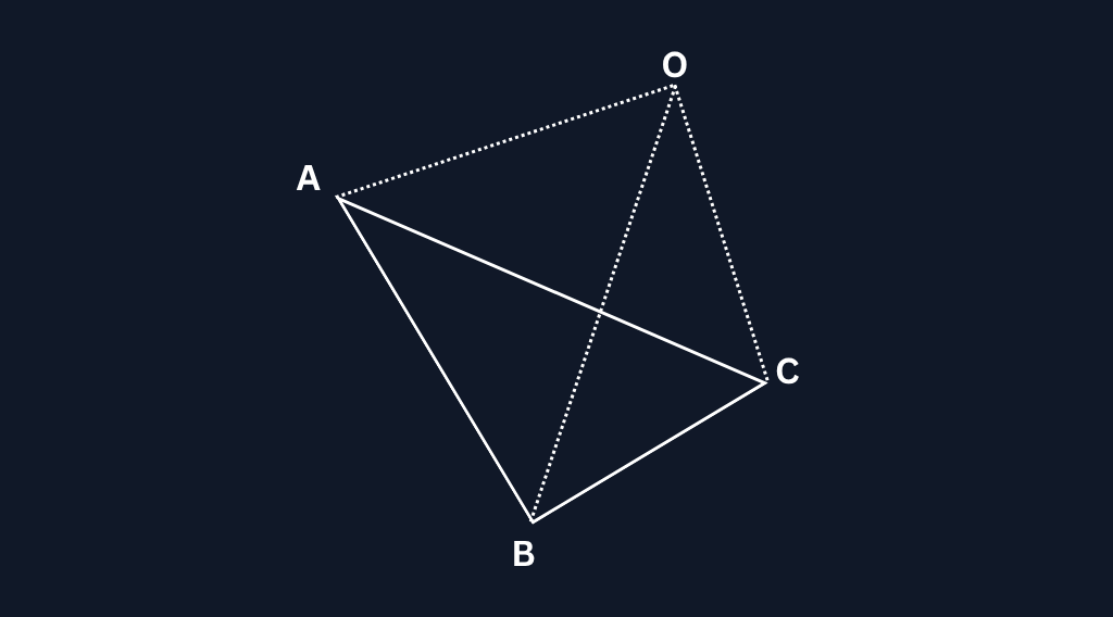
If we use this volume to calculate the volume of the model, we would be overestimating the volume because the parallelepiped is larger than the triangle, but if we closely observe the parallelepiped, we can see that its volume is equivalent to six times the volume of the tetrahedron OABC.
If you are confused behind the reasoning of this, I would recommend reading this Reddit thread.It explains about decomposing a parallelepiped into six tetrahedra of equal volume.
So the volume of the tetrahedron formed by the vectors A, B and C is given by the formula:
V_{tetrahedron} = \frac{1}{6} |det(M)|
This tetrahedron is formed by the triangle ABC and the origin O(0,0,0).
So now we have a way to calculate the volume of a tetrahedron formed by a triangle and the origin. To calculate the volume of the entire model, we can sum up the volumes of all the tetrahedrons formed by each triangle in the model and the origin.
But there is a catch here. The origin may not be inside the model, so some of the tetrahedrons will be outside the model. To account for this, we can use the concept of signed volume.
You might be wondering how something called volume can have a sign, because you have learned your entire life that volume is a scalar. The idea here is different from physical volume. In computational geometry we use a signed volume to keep track of orientation. The value can be positive or negative depending on the order of the triangle vertices. This does not mean the object has negative physical volume, it is just a mathematical tool that helps us correctly add and cancel tetrahedra when the origin is outside the model.
The sign comes from the winding direction of the triangle. When the vertices are listed in the right-handed order the signed volume becomes positive. When the vertices are listed in the left-handed order the signed volume becomes negative. STL files already expect a consistent winding rule, so the sign naturally tells us whether a triangle contributes positively or negatively when we build tetrahedra with the origin.
Keep the winding direction in mind, we will need it later when clarifying about the limitations of this method.
So the signed volume of the tetrahedron formed by the triangle ABC and the origin O is given by the formula:
V_{signed\_tetrahedron} = \frac{1}{6} det(M) Where det(M) is the determinant of the matrix M.
Determinant det(M) can be calculated using the relationship between the determinant and the scalar triple product of vectors.
det(M) = \textbf{A} \cdot (\textbf{B} \times \textbf{C})
So the signed volume of the tetrahedron can be calculated using the formula:
V_{signed\_tetrahedron} = \frac{1}{6} \textbf{A} \cdot (\textbf{B} \times \textbf{C})
For those who are new to cross and dot products I will provide you with a brief explanation on what is going on here.
The cross product of two vectors results in a vector that is perpendicular to both of the original vectors. The magnitude of this new vector is equal to the area of the parallelogram formed by the two original vectors.
The dot product of two vectors results in a scalar value that represents the magnitude of one vector projected onto another vector.
The volume of the parallelepiped can be also given by the formula:
V_{parallelepiped} = Area_{base} \times height
Now suppose that the cross product of the vectors B and C is V.
\textbf{V} = \textbf{B} \times \textbf{C}
So according to what we discussed above, the magnitude of the vector V is equal to the area of the parallelogram formed by the vectors B and C.
|\textbf{V}| = Area_{base}
Now when we take the dot product of the vector A with the vector V, we are projecting the vector A onto the vector V. The result is a scalar value that represents the magnitude of the vector A in the direction of the vector V. This scalar value is equal to the height of the parallelepiped when the base is defined by the vectors B and C.
This is mainly the intuition behind why the volume of the parallelepiped can be calculated using the scalar triple product of the vectors A, B and C.
If you are still confused about the idea maybe you need to learn cross product and dot products more deeply, without just memorizing the formulas. I would recommend the below resources for that:
- Dot product - 3Blue 1Brown
- Cross product - 3Blue 1Brown
- Cross product and transformations - 3Blue 1Brown
- Scalar Triple Product - Wikipedia
Now that we have a way to calculate the signed volume of a tetrahedron formed by a triangle and the origin, we can calculate the volume of the entire model by summing up the signed volumes of all the tetrahedrons formed by each triangle in the model and the origin.
V_{model} = \sum_{i=1}^{n} V_{signed\_tetrahedron_i}
Below is the Rust code to sum up the signed volumes of all the tetrahedeons
pub fn volume(triangles: &[model::Triangle]) -> f64 {
    triangles
        .iter()
        .map(|triangle| triangle.signed_volume())
        .sum::<f64>()
        .abs()
}
Source Code Note: The complete implementation for volume calculation, including Kahan summation and parallel processing, is available on GitHub: VinukaThejana/slicer_rs.
Do you notice something off ?
Let’s consider the below code snippet:
let mut sum = 1_000_000.0;
// the volume of the tetrahedron is very small to make an effect on the sum
sum += 0.0001; // on f64 this might not have an effect
This might not be an issue if you just adding a few tetrahedrons, but when you are adding thousands of them, error adds up. We can use the Kahan summation algorithm to reduce the numerical error when adding a sequence of floating point numbers.
This works as follows:
pub fn kahan_sum(values: &[f64]) -> f64 {
    let mut sum = 0.0;
    let mut compensation = 0.0;

    for &value in values {
        let y = value - compensation; // compensated value
        let t = sum + y; // new sum
        compensation = (t - sum) - y; // lost precision
        sum = t;
    }

    sum
}
Source Code Note: The complete implementation for volume calculation, including Kahan summation and parallel processing, is available on GitHub: VinukaThejana/slicer_rs.
This algorithm keeps track of small errors that occur during the addition process and compensates for them in subsequent additions, resulting in a more accurate final sum.
The above code can be optimized to process triangles in parallel and it can be written as:
pub fn volume(triangles: &[model::Triangle]) -> f64 {
    if triangles.is_empty() {
        return 0.0;
    }

    // parallelization is not efficient for a small number of triangles
    // so if the triangle count exceeds the threshold limit
    // only then apply parallelization
    const PARALLEL_THRESHOLD: usize = 1000;
    const CHUNK_SIZE: usize = 1000;

    let total_volume: f64 = if triangles.len() >= PARALLEL_THRESHOLD {
        triangles.par_chunks(CHUNK_SIZE).map(kahan_sum).sum()
    } else {
        kahan_sum(triangles)
    };

    total_volume.abs()
}

#[inline] // hints the compiler to inline the function if needed
fn kahan_sum(triangles: &[model::Triangle]) -> f64 {
    let mut sum = 0.0f64;
    let mut compensation = 0.0f64;

    for triangle in triangles {
        let y = triangle.signed_volume() - compensation;
        let t = sum + y;
        compensation = (t - sum) - y;
        sum = t;
    }

    sum
}
Source Code Note: The complete implementation for volume calculation, including Kahan summation and parallel processing, is available on GitHub: VinukaThejana/slicer_rs.
What about other file formats ?
File formats like OBJ and PLY can contain polygons with more than 3 vertices (n-polygons; polygons with n vertices). Calculating the volume of polygons with various number of vertices can be very complex.
To simplify the process, we can use a technique called triangulation. Triangulation is the process of dividing a polygon into multiple triangles. Once we have triangulated the polygons, we can apply the same method we used for triangles to calculate the volume of the model.
Convex vs Concave Models
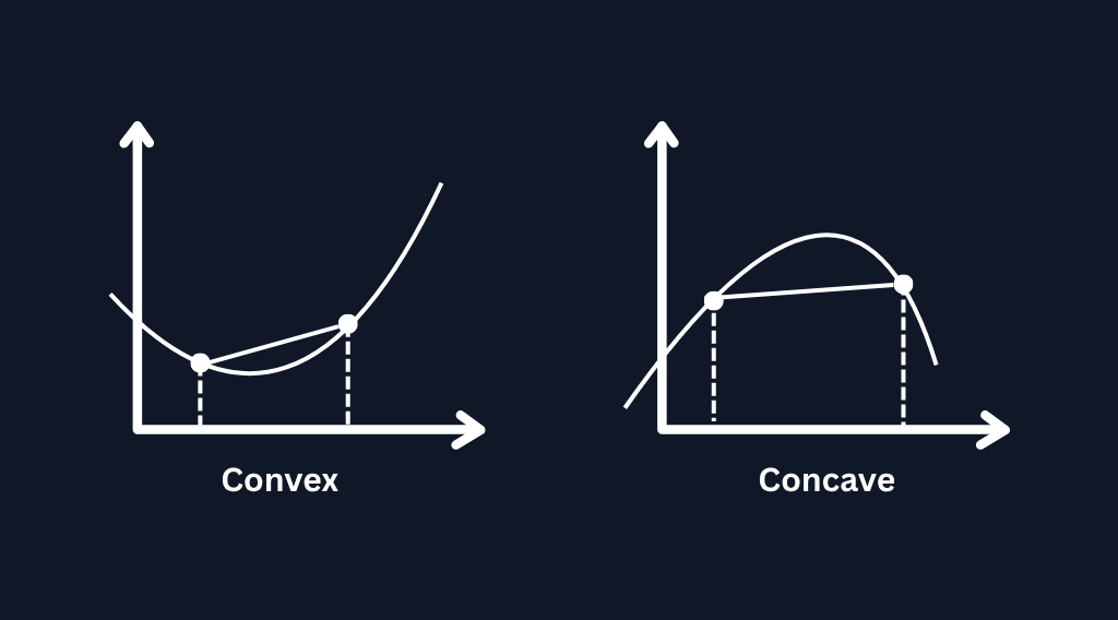
Before we move any further, it is important to understand the difference between convex and concave models.
A convex model is one where any line segment drawn between two points inside the object remains entirely inside the object. In other words, the surface always bends outwards, there are no inward dents or pockets.
A concave model is the opposite, it has regions where the surface bends inwards, so a line drawn between two interior points might pass outside the object.
Various triangulation algorithms
There are several ways to triangulate a polygon. Some are simple and fast, while others are more complex but give stronger guarantees.Here are some common methods that you may come across:
This is the simplest way to triangulate a polygon. You pick one vertex as a pivot, then form triangles by connecting the pivot to every pair of consecutive vertices. This works perfectly for convex polygons because all triangles stay inside the shape.
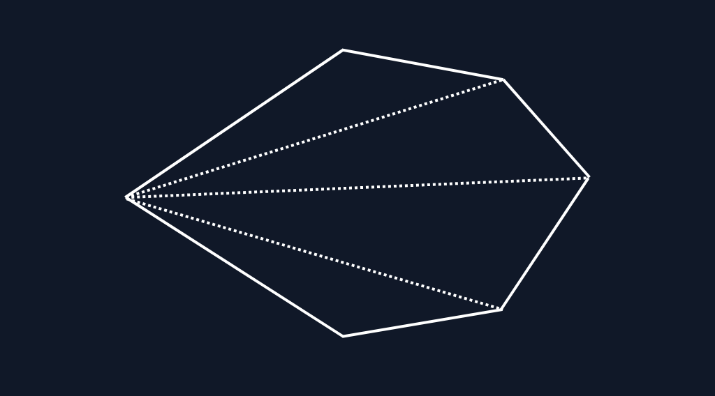
The problem is, most polygons in real 3D models are not guaranteed to be convex. When the polygon is concave, the fan method produces triangles that fall outside the shape, which breaks the volume calculation. So although the fan method is fast and easy, it is not reliable for general OBJ or PLY files.
Ear clipping repeatedly finds and removes “ears” which are triangles formed by three consecutive vertices that do not contain any other vertex inside them.This makes it work correctly for concave polygons as well, not just convex ones. It does not need preprocessing or special conditions, and it works directly on the ordered vertex list found in common 3D model formats. Because of this, it is the most practical method for triangulating polygon faces when computing volume.
To mark a triangle as an ear, we need to check two conditions:
- The angle formed by the three vertices is convex.
- No other vertex of the polygon lies inside the triangle.
I would recommend reading this paper for a deep dive into the ear clipping method.
So we will use the ear clipping method to triangulate polygons in OBJ and other files before calculating the volume using the tetrahedron method described earlier.
Below given is the rust code to calculate the volume of a model with polygons using the ear clipping method for triangulation:
use crate::{
    calculate::{Vec2, Vec3},
    error::AppError,
};

pub struct Triangle {
    pub vertices: [Vec3; 3],
}

// calculate the polygon normal using Newell's method
// this is used to determine the dominant axis for projection
fn compute_polygon_normal(vertices: &[Vec3], indices: &[usize]) -> Vec3 {
    let mut nx = 0.0;
    let mut ny = 0.0;
    let mut nz = 0.0;

    // Newell's method
    // https://www.khronos.org/opengl/wiki/Calculating_a_Surface_Normal
    for win in indices.windows(2) {
        let v0 = &vertices[win[0]];
        let v1 = &vertices[win[1]];

        nx += (v0.1 - v1.1) * (v0.2 + v1.2);
        ny += (v0.2 - v1.2) * (v0.0 + v1.0);
        nz += (v0.0 - v1.0) * (v0.1 + v1.1);
    }

    // close the polygon
    // last vertex to first vertex
    if indices.len() > 1 {
        // last vertex
        let v0 = &vertices[indices[indices.len() - 1]];
        // first vertex
        let v1 = &vertices[indices[0]];

        // same accumulation formula
        nx += (v0.1 - v1.1) * (v0.2 + v1.2);
        ny += (v0.2 - v1.2) * (v0.0 + v1.0);
        nz += (v0.0 - v1.0) * (v0.1 + v1.1);
    }

    Vec3(nx, ny, nz)
}

// pick the dominant axis (0: X, 1: Y, 2: Z) for projection
fn pick_dominant_axis(normal: Vec3) -> u8 {
    let ax = normal.0.abs();
    let ay = normal.1.abs();
    let az = normal.2.abs();

    if ax > ay && ax > az {
        0
    } else if ay > az {
        1
    } else {
        2
    }
}

// project 3D vertices to 2D plane based on the dominant axis
fn project_to_2d(vertices: &[Vec3], indices: &[usize]) -> Vec<Vec2> {
    let normal = compute_polygon_normal(vertices, indices);
    let axis = pick_dominant_axis(normal);

    indices
        .iter()
        .map(|i| {
            let v = &vertices[*i];
            match axis {
                0 => Vec2(v.1, v.2), // project to YZ plane
                1 => Vec2(v.0, v.2), // project to XZ plane
                _ => Vec2(v.0, v.1), // project to XY plane
            }
        })
        .collect()
}

// check if the angle formed by the vertices prev-curr-next is convex
fn is_convex(prev: Vec2, curr: Vec2, next: Vec2, winding_positive: bool) -> bool {
    let cross = (curr.substraction(prev)).cross(next.substraction(curr));
    if winding_positive {
        cross > 0.0
    } else {
        cross < 0.0
    }
}

// check if a point is inside a triangle using barycentric coordinates
// https://mathworld.wolfram.com/BarycentricCoordinates.html
fn point_in_triangle(point: Vec2, a: Vec2, b: Vec2, c: Vec2) -> bool {
    let v0 = b.substraction(a);
    let v1 = c.substraction(a);
    let v2 = point.substraction(a);

    let dot00 = v0.dot(v0); // ||v0||²
    let dot01 = v0.dot(v1); // v0 · v1
    let dot02 = v0.dot(v2); // v0 · v2
    let dot11 = v1.dot(v1); // ||v1||²
    let dot12 = v1.dot(v2); // v1 · v2

    // Barycentric coordinates
    let denom = dot00 * dot11 - dot01 * dot01;
    if denom.abs() < f32::EPSILON {
        // triangle is degenerate (AKA No measurable area)
        return false;
    }

    let inv_denom = 1.0 / denom;
    let u = (dot11 * dot02 - dot01 * dot12) * inv_denom;
    let v = (dot00 * dot12 - dot01 * dot02) * inv_denom;

    (u >= 0.0) && (v >= 0.0) && (u + v <= 1.0)
}

// Polygon triangulation using Ear clipping algorithm
// https://www.geometrictools.com/Documentation/TriangulationByEarClipping.pdf
pub fn triangulate(vertices: &[Vec3], indices: &[usize]) -> Result<Vec<Triangle>, AppError> {
    if indices.len() < 3 {
        return Err(AppError::bad_request(
            "cannot triangulate polygon with less than 3 vertices",
        ));
    }

    let projection = project_to_2d(vertices, indices);

    let winding_positive = {
        // determine polygon winding order by calculating signed area
        // using the shoelace formula
        // https://en.wikipedia.org/wiki/Shoelace_formula
        let mut area = 0.0;
        for i in 0..projection.len() {
            let a = &projection[i];
            let b = &projection[(i + 1) % projection.len()];
            area += a.0 * b.1 - b.0 * a.1;
        }
        area > 0.0
    };

    let mut active_indices: Vec<usize> = (0..indices.len()).collect();
    let mut triangles = Vec::with_capacity(indices.len() - 2);

    let mut i = 0;
    let mut remaining_vertices = active_indices.len();
    let mut loop_count = 0;

    while remaining_vertices > 3 {
        loop_count += 1;
        if loop_count > 2 * (remaining_vertices * remaining_vertices) {
            return Err(AppError::bad_request(
                "failed to triangulate polygon: possible non-simple polygon",
            ));
        }

        let prev_idx = (i + remaining_vertices - 1) % remaining_vertices;
        let next_idx = (i + 1) % remaining_vertices;

        let prev = projection[active_indices[prev_idx]];
        let curr = projection[active_indices[i]];
        let next = projection[active_indices[next_idx]];

        // Not an Ear, try the next vertex
        if !is_convex(prev, curr, next, winding_positive) {
            i = (i + 1) % remaining_vertices;
            continue;
        }

        // Check if any other vertex is inside the triangle
        let mut inside = false;
        for (j, &pj) in active_indices.iter().enumerate() {
            // skip the triangle vertices
            if j == prev_idx || j == i || j == next_idx {
                continue;
            }
            if point_in_triangle(projection[pj], prev, curr, next) {
                inside = true;
                break;
            }
        }
        // Not an Ear, try the next vertex
        // Some other vertex is inside the triangle
        if inside {
            i = (i + 1) % remaining_vertices;
            continue;
        }

        triangles.push(Triangle {
            vertices: [
                vertices[indices[active_indices[prev_idx]]],
                vertices[indices[active_indices[i]]],
                vertices[indices[active_indices[next_idx]]],
            ],
        });
        // remove the ear vertex
        active_indices.remove(i);
        remaining_vertices -= 1;
        i %= remaining_vertices;
        loop_count = 0;
    }

    // add the last triangle
    let a = active_indices[0];
    let b = active_indices[1];
    let c = active_indices[2];

    triangles.push(Triangle {
        vertices: [
            vertices[indices[a]],
            vertices[indices[b]],
            vertices[indices[c]],
        ],
    });

    Ok(triangles)
}
Source Code Note: The complete implementation for volume calculation, including Kahan summation and parallel processing, is available on GitHub: VinukaThejana/slicer_rs.
In the above code you may notice that we are projecting the 3D vertices to a 2D plane before performing the ear clipping algorithm. This is because the ear clipping algorithm works on 2D polygons. By projecting the 3D vertices to a 2D plane, we can apply the ear clipping algorithm to triangulate the polygon.
If you are not comfortable with the 3D->2D transformations, I would recommend watching the video on 3D transformations by 3Blue 1Brown.
A small discovery I made later
While building this and writing the blog, I was strictly focused on getting the geometry right. That is why I implemented the Ear Clipping method above, it guarantees that every generated triangle is valid and sits inside the polygon.
But I found out something interesting later.
If our primary goal is just calculating the volume, we can actually get away with using the Fan Triangulation method I mentioned earlier (the one I said we shouldn’t use!).
Since we are using signed volume, the math sorts itself out. When fan triangulation creates a triangle that falls “outside” a concave polygon, the winding direction of that specific triangle gets reversed relative to the pivot. This generates a negative volume that perfectly cancels out the excess.
I realized this only after implementing complex logic for the Ear Clipping Algorithm.
- Ear Clipping: Essential if you need valid geometry (for rendering or collision).
- Fan Triangulation: Perfectly fine for volume calculation and is much faster (O(n)).
Limitations of this method
-
When calculating the volume we assume that the polygons are interconnected through vertices or faces, therefore the mesh needs to be watertight. This means there should not be any gap between the polygons.
-
I hope that you can remember the winding direction mentioned above. For this volume calculation logic to work, this winding direction should be consistent throughout the file. That means if the winding direction is clockwise it should be clockwise throughout the file, and vice-versa.